


Send Message
Privacy-ferklearring: Jo privacy is heul wichtich foar ús. Us bedriuw belooft net om jo persoanlike ynformaasje te iepenbierjen oan elke eksplisytrjochten út.
Model nûmer.: NSO4GU3AB
Transport: Ocean,Air,Express,Land
Betel wize: L/C,T/T,D/A
Incoterm: FOB,EXW,CIF
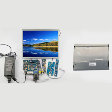
4GB 1600MHz 240-Pin Ddr3 Udimm
Ferzje skiednis
|
Revision No. |
History |
Draft Date |
Remark |
|
1.0 |
Initial Release |
Apr. 2022 |
|
![]()
Ynformaasje tafel bestelle
|
Model |
Density |
Speed |
Organization |
Component Composition |
|
NS04GU3AB |
4GB |
1600MHz |
512Mx64bit |
DDR3 256Mx8 *16 |
Beskriuwing
Hengstar unbuffered DDR3 SDRAM DIMMS (unbufferde Dûbele gegevens taryf DOINCHRONUS DIM DIDUAL IN-LINE MEIDY FERGESE EARMAGE ISRINE WERKE MEINTIONSOGNEN MOOREGOPTIONS DAT DDR3 SDRAM-apparaten brûke. NS04VU3AB is in 512m X 64-bit twa-rang 4GB DDR3-1600 CL11 1.5V SDRAM Unbuiende Dimm Produkt, basearre op sechstjin 256m X 8-bit fbga-komponinten. De SPD is programmearre nei Jedlec Standert Laty DDR3-1600 TIMING FAN 11-11-11 AT 1.5V. Elke 240-PIN Dimm brûkt Gouden kontaktpersoanen. De SDRAM unbufferde dimm is bedoeld foar gebrûk as haadgeheugen by ynstalleare by ynstalleare yn systemen lykas PC's en wurkstasjons.
Funksjes
Power Supplances: VDD = 1,5v (1.425v nei 1.575V)
vddq = 1,5v (1,425V nei 1.575V)
800mhz FCK foar 1600MB / SEC / PIN
8 Unôfhinklike ynterne bank
programma's CAS LATENCY: 11, 10, 9, 8, 7, 6
programmerable tafoegjend latency: 0, CL - 2, OF of CL - 1 klok
8-bit foarôf
BURST Lengte: 8 (Interleave sûnder limyt, sekwinsjoneel mei begjinadres "000" allinich), 4 mei TCCD = 4 dy't naadleaze lês of skriuwe [op 'e flecht mei A12 of Mrs]
Ębi-directional differinsjele gegevens strobe
internal (Sels) kalibraasje; Ynterne Self-kalibraasje fia ZQ PIN (RZQ: 240 ohm ± 1%)
ons Die Beëiniging mei ODT PIN
Refferjeperioade 7,8us op legere dan Tase dan Tase 85 ° C, 3,9U's om 85 ° C <Tase <95 ° C
asynchronous reset
ADADUNDABLE DATA-OUSPUP DRIVE SKROLD
fly-by topology
pcb: hichte 1.18 "(30mm)
rohs foldwaan en halogen-frij
Key Timing Parameters
|
MT/s |
tRCD(ns) |
tRP(ns) |
tRC(ns) |
CL-tRCD-tRP |
|
DDR3-1600 |
13.125 |
13.125 |
48.125 |
2011/11/11 |
Adres Tabel
|
Configuration |
Refresh count |
Row address |
Device bank address |
Device configuration |
Column Address |
Module rank address |
|
4GB |
8K |
32K A[14:0] |
8 BA[2:0] |
2Gb (256 Meg x 8) |
1K A[9:0] |
2 S#[1:0] |
Pin beskriuwingen
|
Symbol |
Type |
Description |
|
Ax |
Input |
Address inputs: Provide the row address for ACTIVE commands, and the column |
|
BAx |
Input |
Bank address inputs: Define the device bank to which an ACTIVE, READ, WRITE, or |
|
CKx, |
Input |
Clock: Differential clock inputs. All control, command, and address input signals are |
|
CKEx |
Input |
Clock enable: Enables (registered HIGH) and disables (registered LOW) internal circuitry |
|
DMx |
Input |
Data mask (x8 devices only): DM is an input mask signal for write data. Input data is |
|
ODTx |
Input |
On-die termination: Enables (registered HIGH) and disables (registered LOW) |
|
Par_In |
Input |
Parity input: Parity bit for Ax, RAS#, CAS#, and WE#. |
|
RAS#, |
Input |
Command inputs: RAS#, CAS#, and WE# (along with S#) define the command being |
|
RESET# |
Input |
Reset: RESET# is an active LOW asychronous input that is connected to each DRAM and |
|
Sx# |
Input |
Chip select: Enables (registered LOW) and disables (registered HIGH) the command |
|
SAx |
Input |
Serial address inputs: Used to configure the temperature sensor/SPD EEPROM address |
|
SCL |
Input |
Serial |
|
CBx |
I/O |
Check bits: Used for system error detection and correction. |
|
DQx |
I/O |
Data input/output: Bidirectional data bus. |
|
DQSx, |
I/O |
Data strobe: Differential data strobes. Output with read data; edge-aligned with read data; |
|
SDA |
I/O |
Serial |
|
TDQSx, |
Output |
Redundant data strobe (x8 devices only): TDQS is enabled/disabled via the LOAD |
|
Err_Out# |
Output (open |
Parity error output: Parity error found on the command and address bus. |
|
EVENT# |
Output (open |
Temperature event: The EVENT# pin is asserted by the temperature sensor when critical |
|
VDD |
Supply |
Power supply: 1.35V (1.283–1.45V) backward-compatible to 1.5V (1.425–1.575V). The |
|
VDDSPD |
Supply |
Temperature sensor/SPD EEPROM power supply: 3.0–3.6V. |
|
VREFCA |
Supply |
Reference voltage: Control, command, and address VDD/2. |
|
VREFDQ |
Supply |
Reference voltage: DQ, DM VDD/2. |
|
VSS |
Supply |
Ground. |
|
VTT |
Supply |
Termination voltage: Used for control, command, and address VDD/2. |
|
NC |
– |
No connect: These pins are not connected on the module. |
|
NF |
– |
No function: These pins are connected within the module, but provide no functionality. |
OPMERKINGEN : DE HJIR PIN BESKRIJVE TABLOCHT HJIR IS EIN WURFFIER FAN ALLE MUSLE PIN FOAR ALLE DDR3 MODULES. Alle Pins fermeld maaie net stipe wurde op dizze module. Sjoch PIN-opdrachten foar ynformaasje spesifyk foar dizze module.
Funksjoneel blokdiagram
4GB, 512MX64 Module (2rank fan X8)


Module-ôfmjittings
Foaroansicht

Foaroansicht

Notysjes:
1. Alle ôfmjittings binne yn Millimeter (inch); Maks / min as typysk (typ) wêr't opmurken is.
2..Solerance op alle dimensjes ± 0,15mm, útsein as oars oantsjutte.
3.De dimensional-diagram is allinich foar referinsje.
Produktkategorien : Industrial Smart Module Accessoires


Privacy-ferklearring: Jo privacy is heul wichtich foar ús. Us bedriuw belooft net om jo persoanlike ynformaasje te iepenbierjen oan elke eksplisytrjochten út.
Folje mear ynformaasje yn sadat kin yn kontakt komme mei jo rapper
Privacy-ferklearring: Jo privacy is heul wichtich foar ús. Us bedriuw belooft net om jo persoanlike ynformaasje te iepenbierjen oan elke eksplisytrjochten út.